
<<<<The lowrider concept
Secondary Ring
As with most of my previous telescopes I started the build by making the secondary ring. After designing the telescope in Sketchup (see the design page) I had a woodworking company CNC all the wooden parts out of birch multiplex. This saved a lot time and ensured that all the components were precisely manufactured.
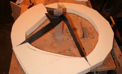
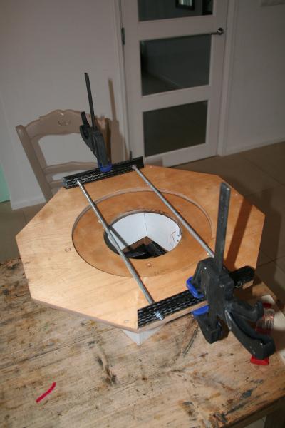
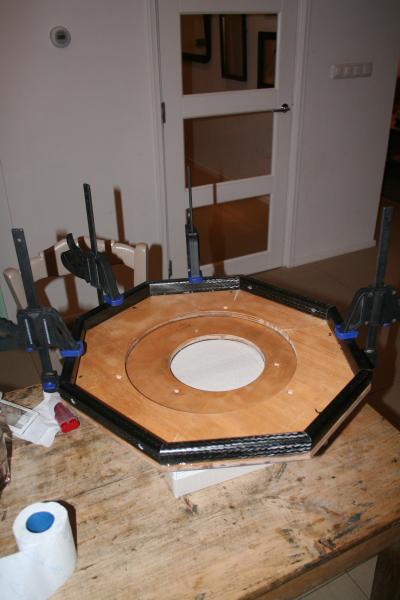
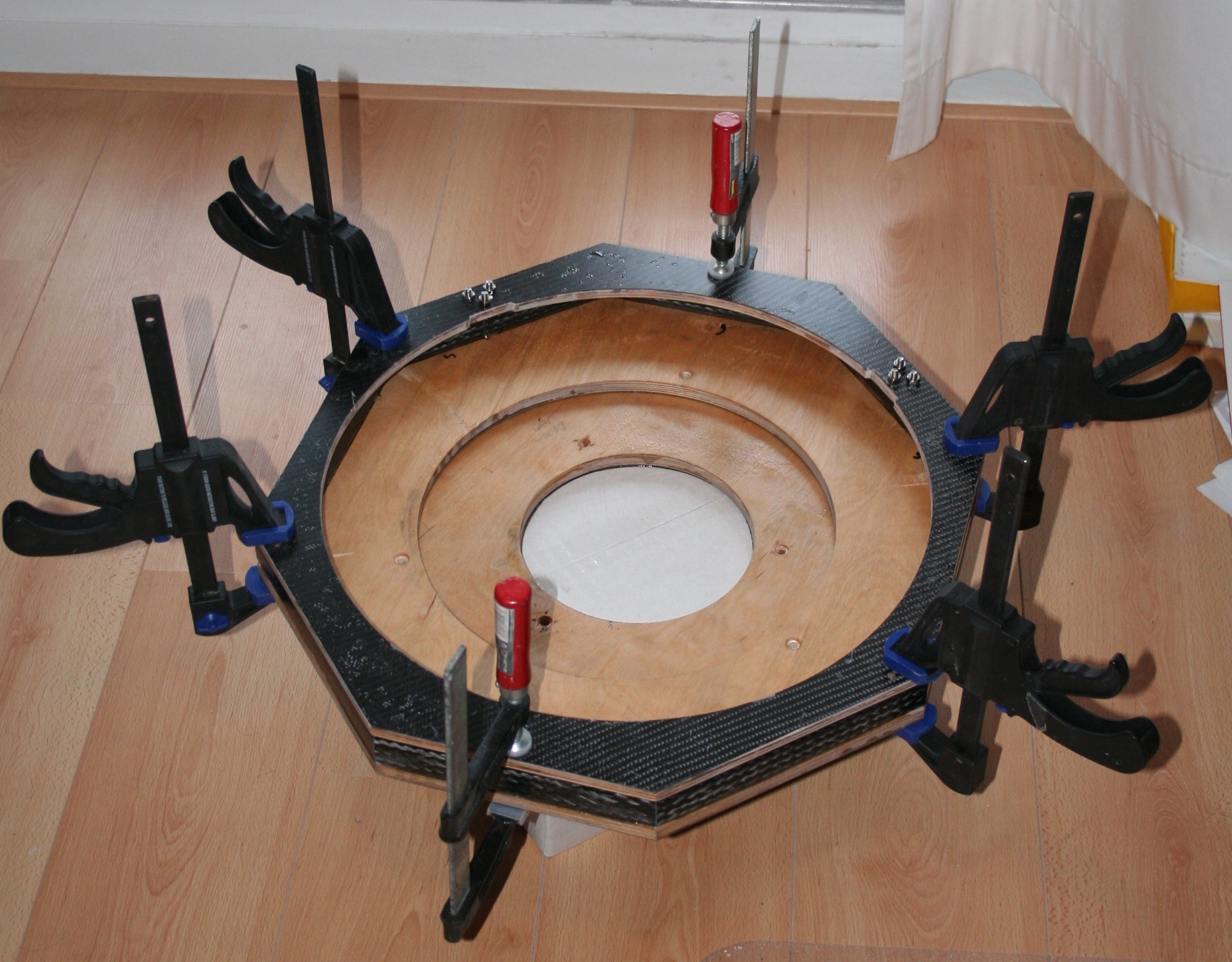
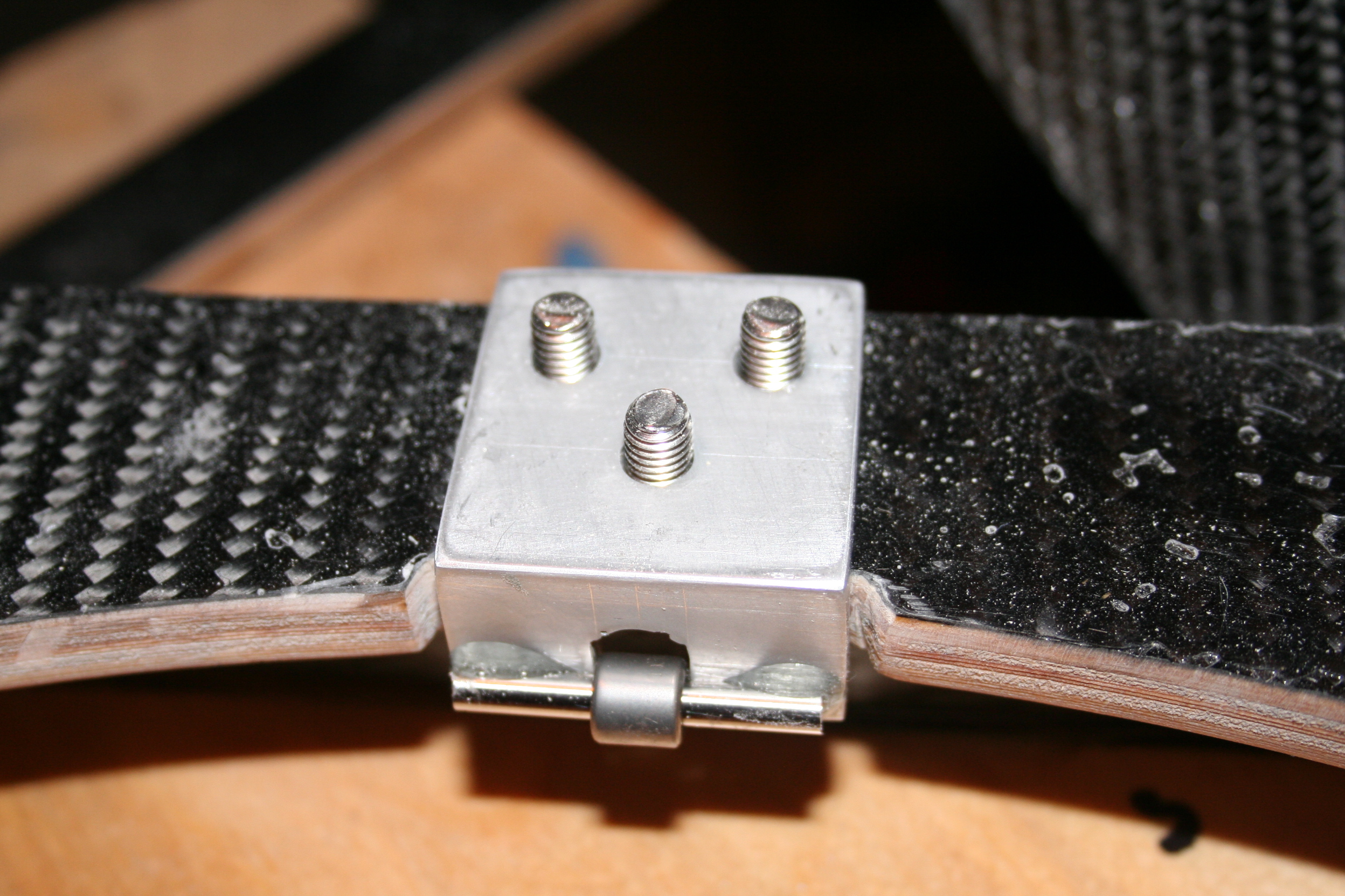
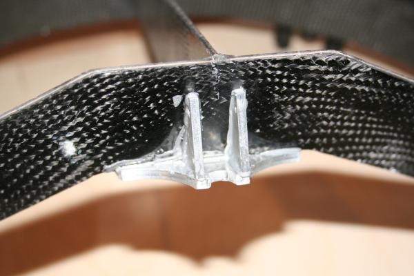
Since I wanted the secondary ring to be as light as possible, I used a sandwich method (see images under figure 7). Basically two 4 mm rings are sandwiching a polyurethane foam core. I first laminated the two rings on one side with carbon fiber and epoxy glue. I proceeded to glue the foam to half of the bottom ring. The central vane was then glued to the side of the foam. After I glued another quarter of the ring with foam the back vane was attached. The vanes are made of 1 mm balsa wood which was laminated with multiple layers of carbon. They ended up being 2 mm thick and are rigid enough for me to add a light shield. Carbon band was used for the outside and inside of the secondary ring.
Figure 7

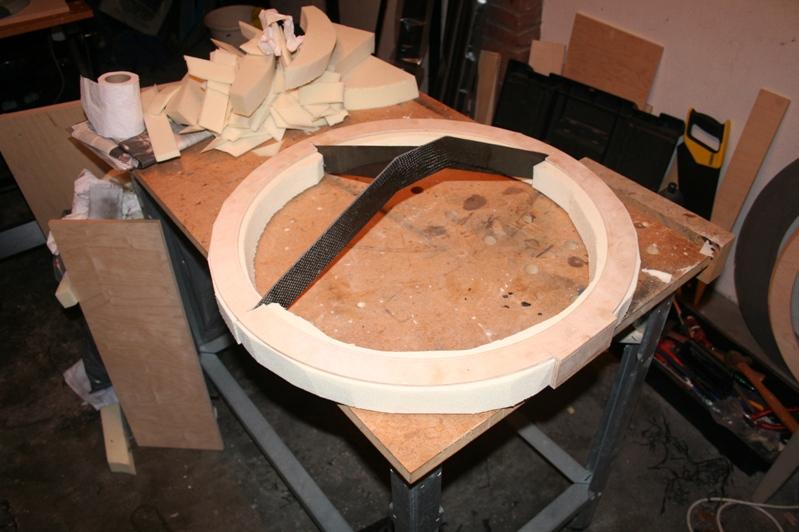
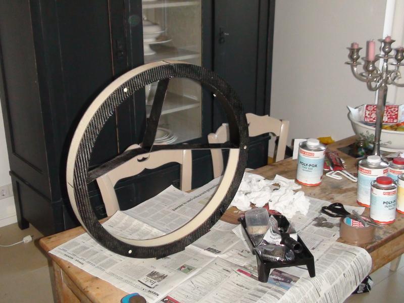

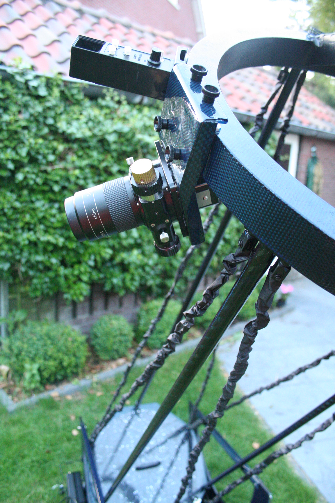
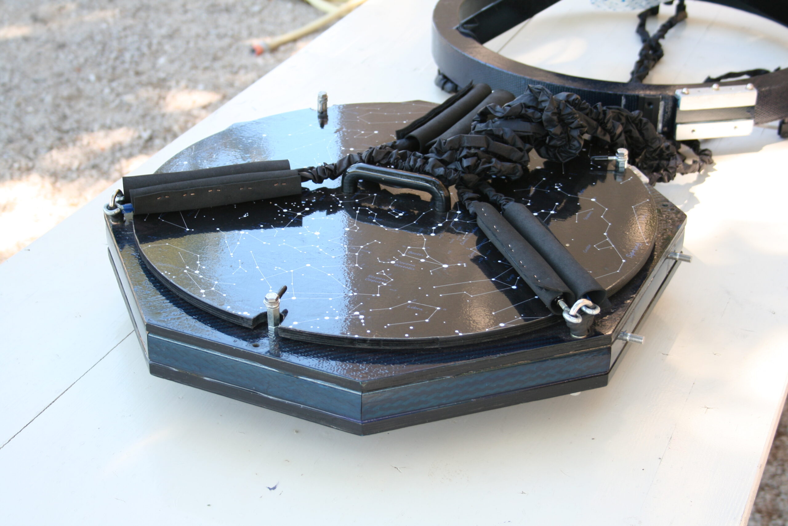
The secondary ring has pyramid shaped vanes because of three reasons. Firstly, it was the only shape could be transported on the mirror box without damaging the secondary mirror. Secondly, in case of a lowrider concept it brings the focuser closer to the secondary ring. And lastly, by lowering the secondary ring the string angle is increased, thus lowering the required force on the strings and poles.
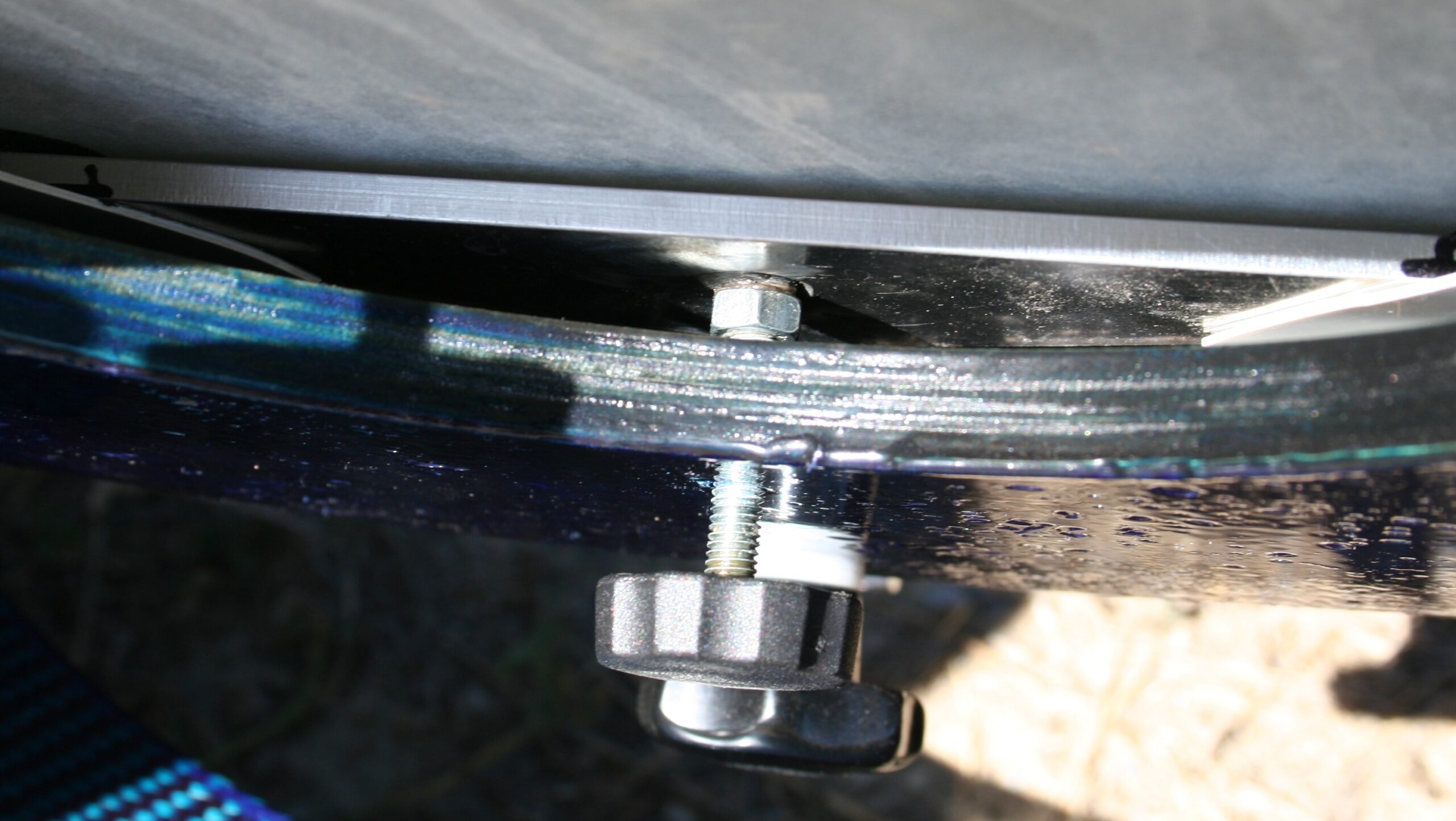
However, because I wanted to place the secondary ring on the mirror box for transport I was forced to make a removable focuser board. This is not advisable because the focuser has to be put back in exactly the same position every time it is removed. Otherwise the focuser needs to be adjusted, which is something you only want to do once. To make sure that the focuser was always in the right position I glued round magnets on a aluminum strip that was glue on the secondary ring (see figure 8).
Figure 8

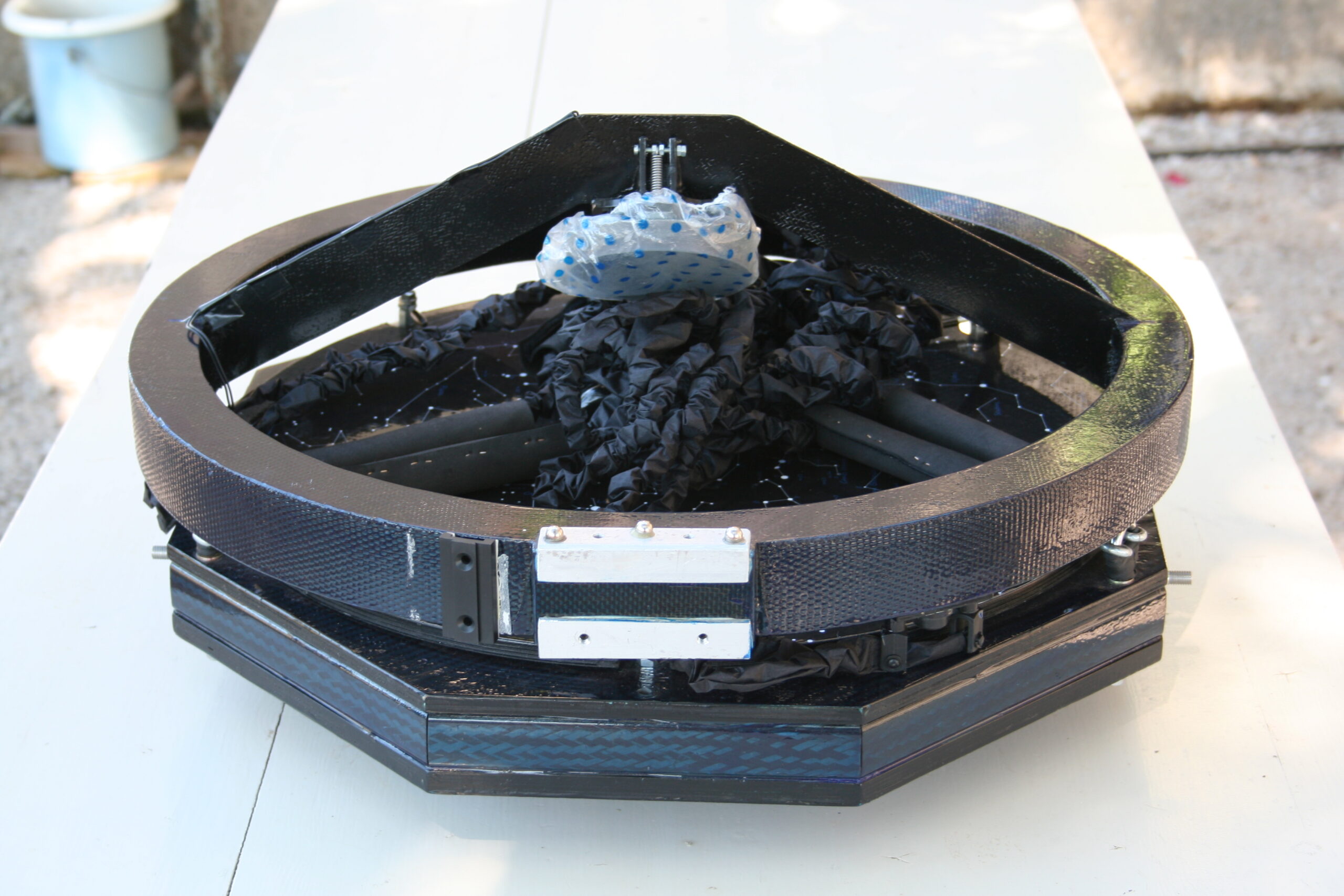
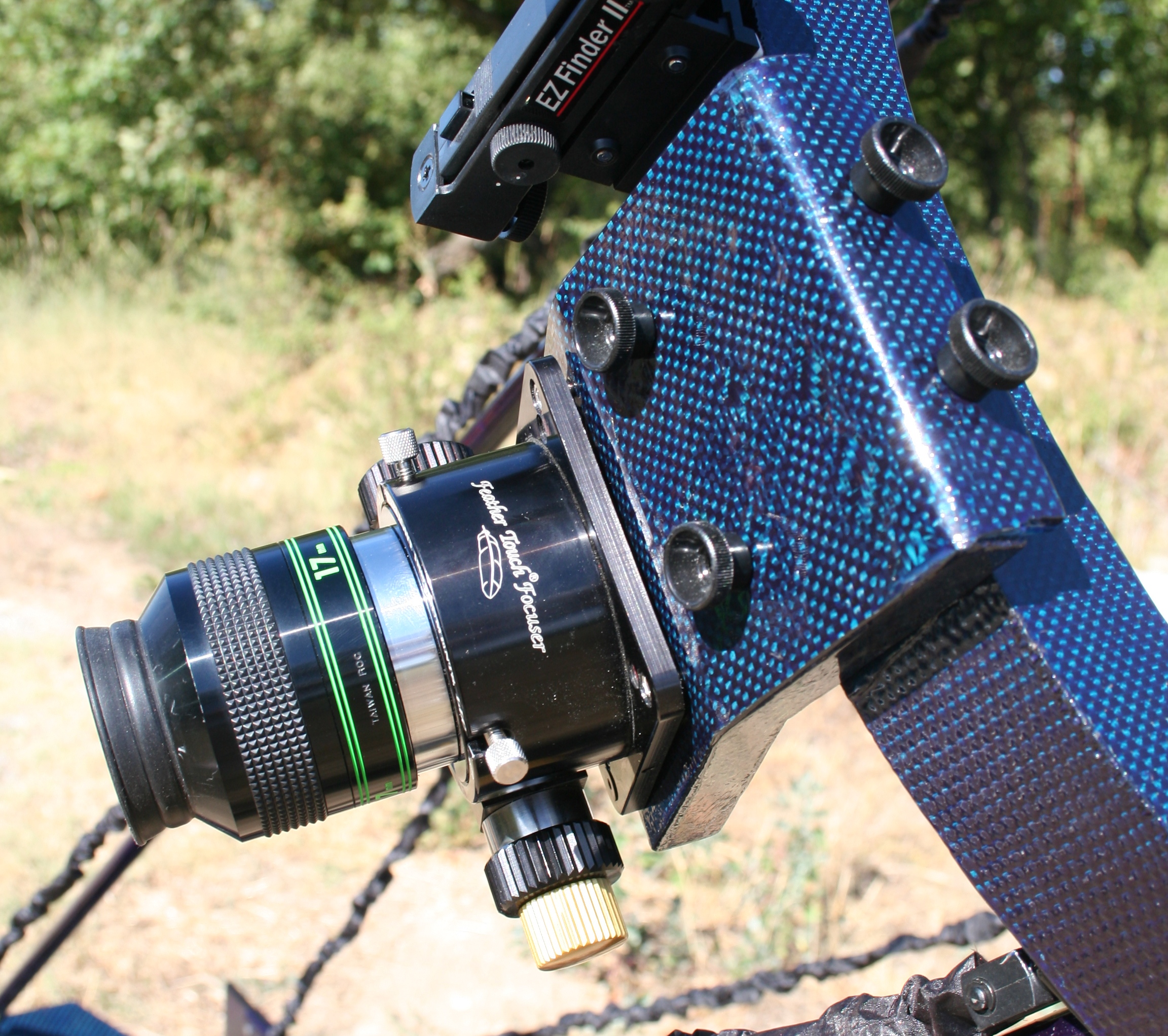
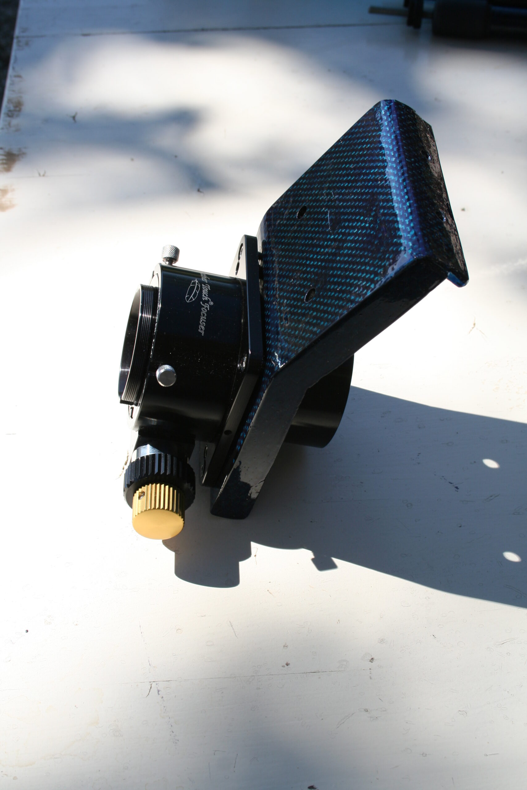
On the inside of the top of the focus board I glue small metal rings in which the balls would fit. This way the focuser board is positioned correctly every time I remove the board (which is after every time I observe).The focuser board was made out of a 3mm thick aluminum plate that was bend and coated with 8 layers of carbon fabric. This resulted in a 6 mm thick plate, which was then strengthened by adding some pieces of carbon to the sides (see figure 9). This component is rigid enough to handle a Feathertouch focuser and a heavy 2 inch eyepiece.
Figure 9
The Mirror Box
Designing this component was the key to building a compact telescope. It needed to be small, both in thickness and width, and it needed to be stiff enough to withstand the pressures that were exerted by the strings and poles. The 6 strings/ 3 poles combination gave me the possibility to bring in the sides of the mirror box, thus creating the asymmetrical shape. This would never be possible with another strings/ poles combination or a truss design. The advantage of this shape is that the mirror box is much easier to lift up for transport, but is also the key to making a smaller rocker box.
The mirror box is an asymmetrical octagon consisting of a bottom plate of 12 mm wood with another smaller plate of 12 mm wood attached to the bottom (see images in figure 10). This created a depression in the mirror box where there was room for the 9 point mirror cell. The wood was laminated with carbon fiber. The walls of the mirror box are made out of carbon profile material. These profiles a normally used to make ice hockey sticks and are extremely strong and light. The top plate was made out of 9 mm wood and also laminated with carbon fiber. The mirror box turned out to be extremely stiff and will not warp no matter how much force is put on the strings.
Figure 10
Mirror Cell
The layout of the 9 point mirror cell was calculated using PLOP software[1] . The mirror cell is very flat (see figure 11). There is only 18 mm space between the bottom of the depression in mirror box and the bottom of the mirror. This is achieved by making a very simple mirror cell.
Figure 11
The three aluminum triangular plates have a round magnet that is glued in a concave depression at the center of gravity. The magnets rest on hollowed out head of a bolt. By turning these bolts thru a T-nut in the bottom of the mirror box, one can tilt the mirror for collimation (see images in figure 12).
Figure 12
Due to spatial constraints the lateral support needed to be small. The lateral support of the mirror consists of a 4 mm thick L-section which is sawed in. An axle with a small bearing was then glued on the L-section (see figure 13). This L-section can be moved a little to adjust the position of the lateral support.
Figure 13
Secondary Mirror & Holder
In a lowrider telescope the secondary mirror is set a different angle then in a classic Newtonian. Since the elliptical shape of most commercially available secondary mirrors is adapted to a 45°, these mirrors do not work well in a lowrider telescope. Most ATMers have used round secondary mirrors for their lowriders. These can be ground, but I decided to have a custom secondary mirror with the correct elliptical shape made by an optical firm. This was not much more expensive than a regular secondary mirror.
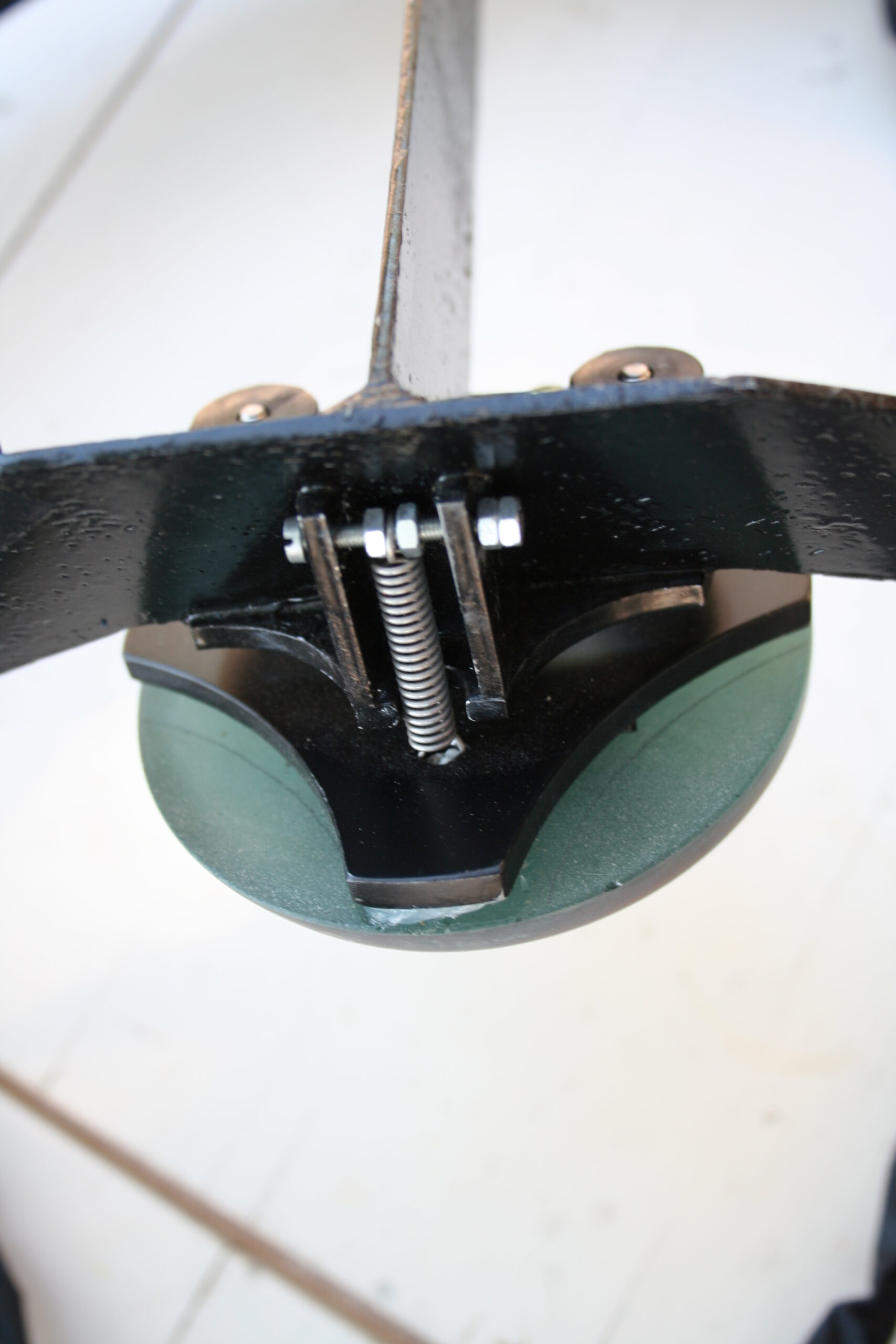
Figure 14
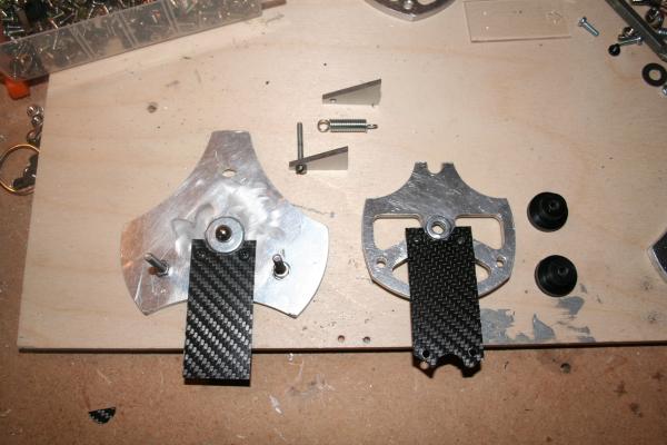
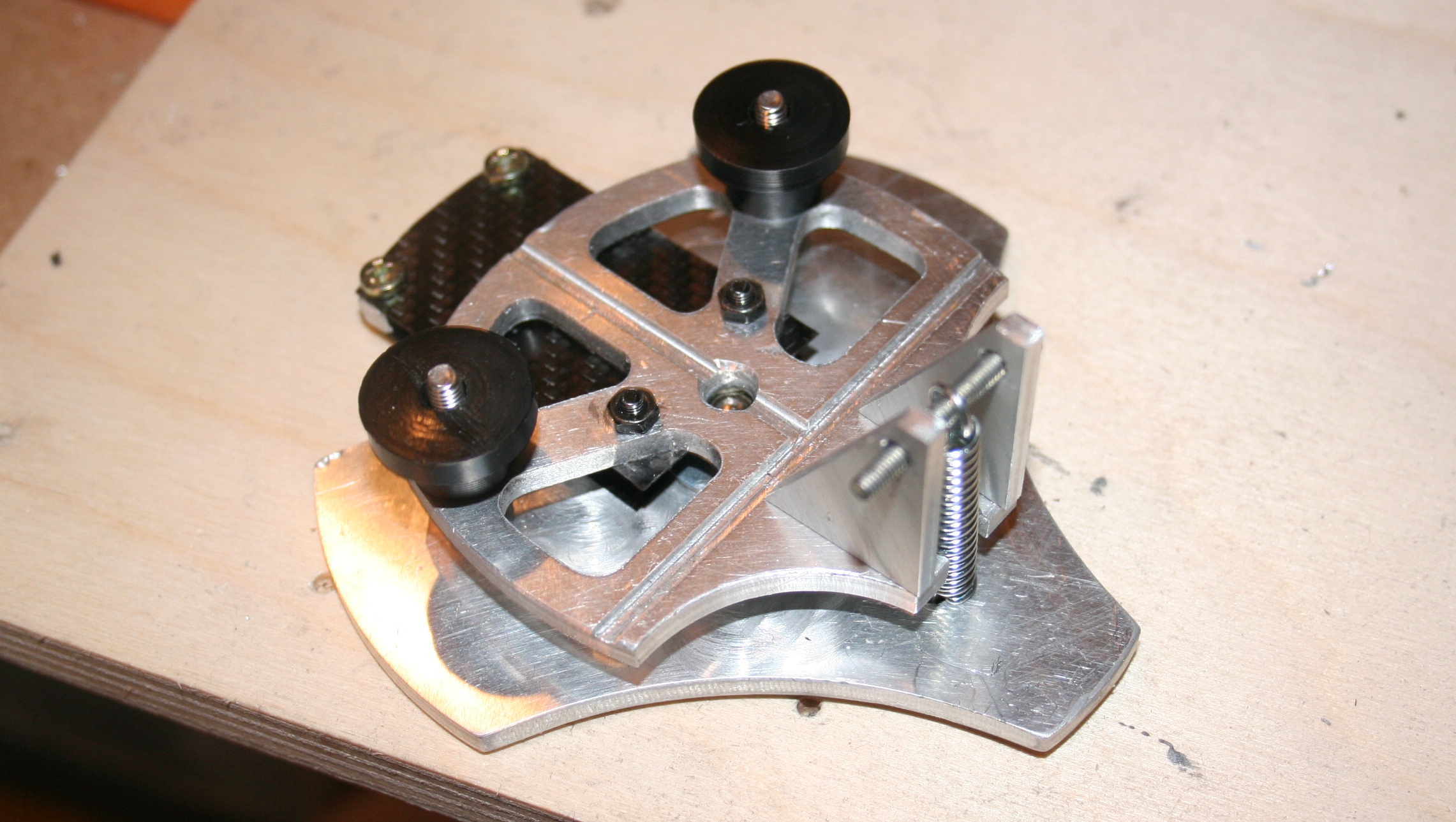
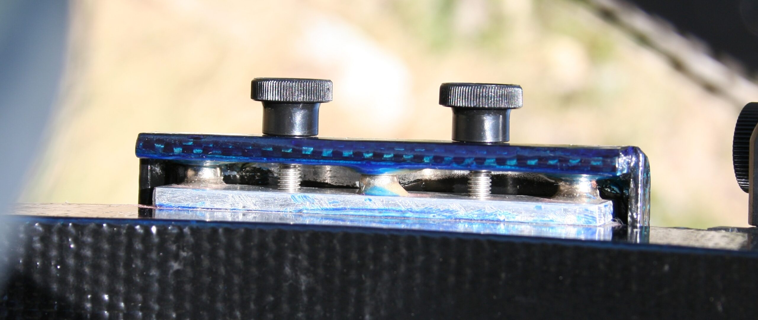
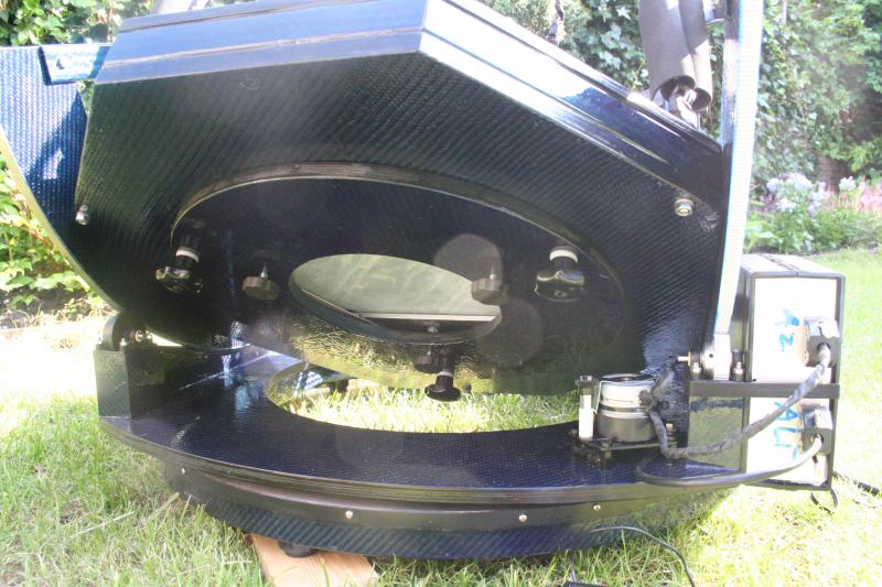
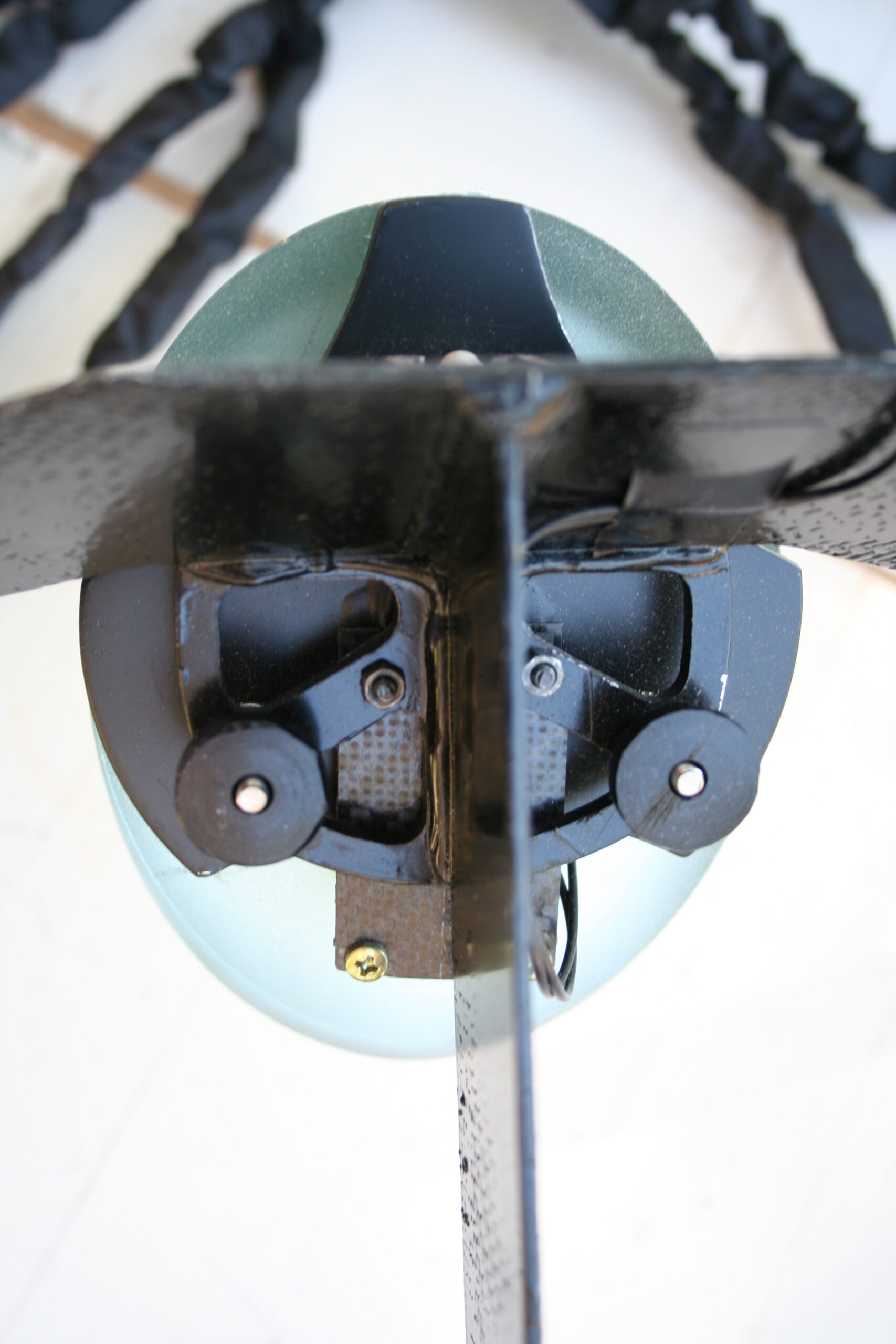
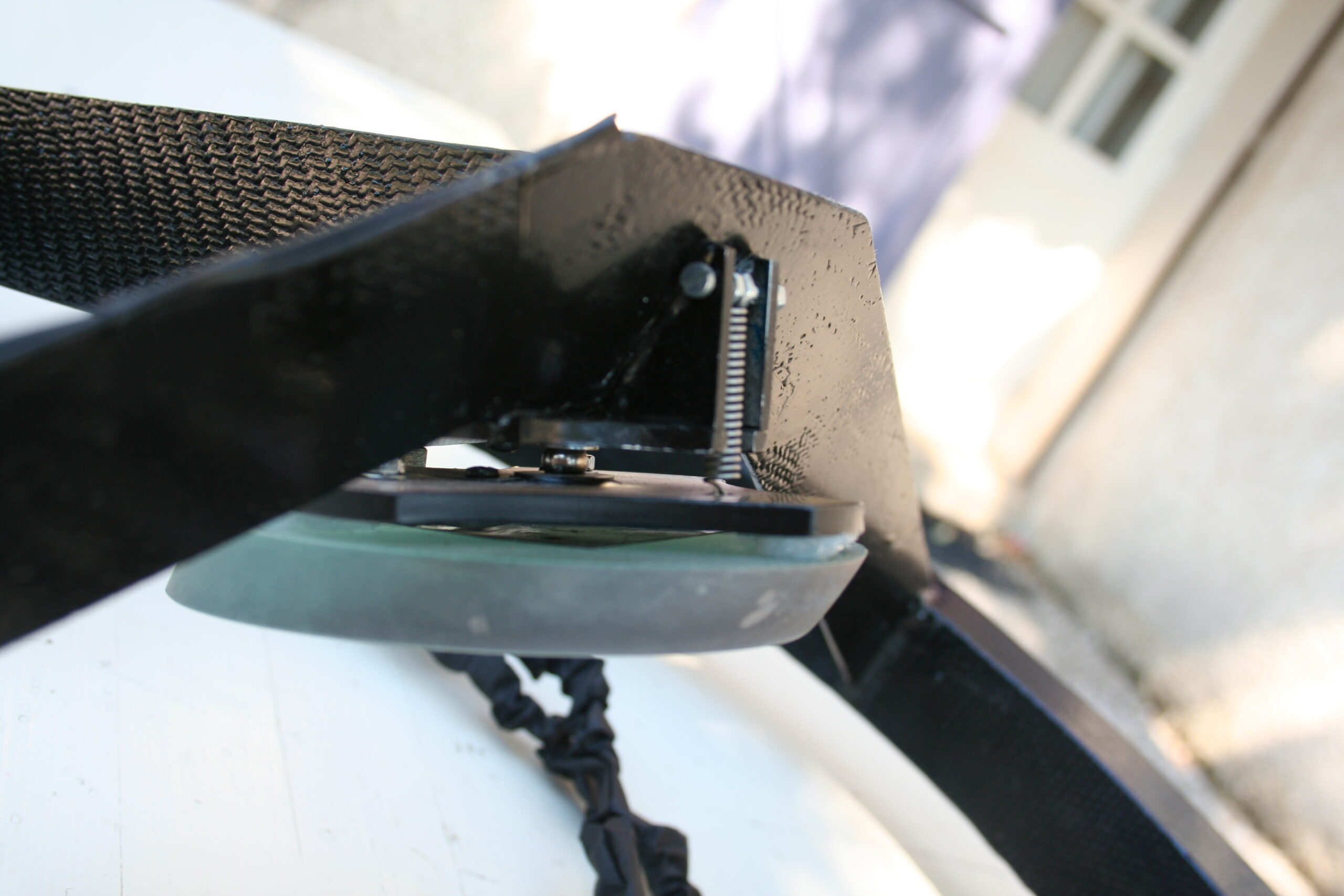
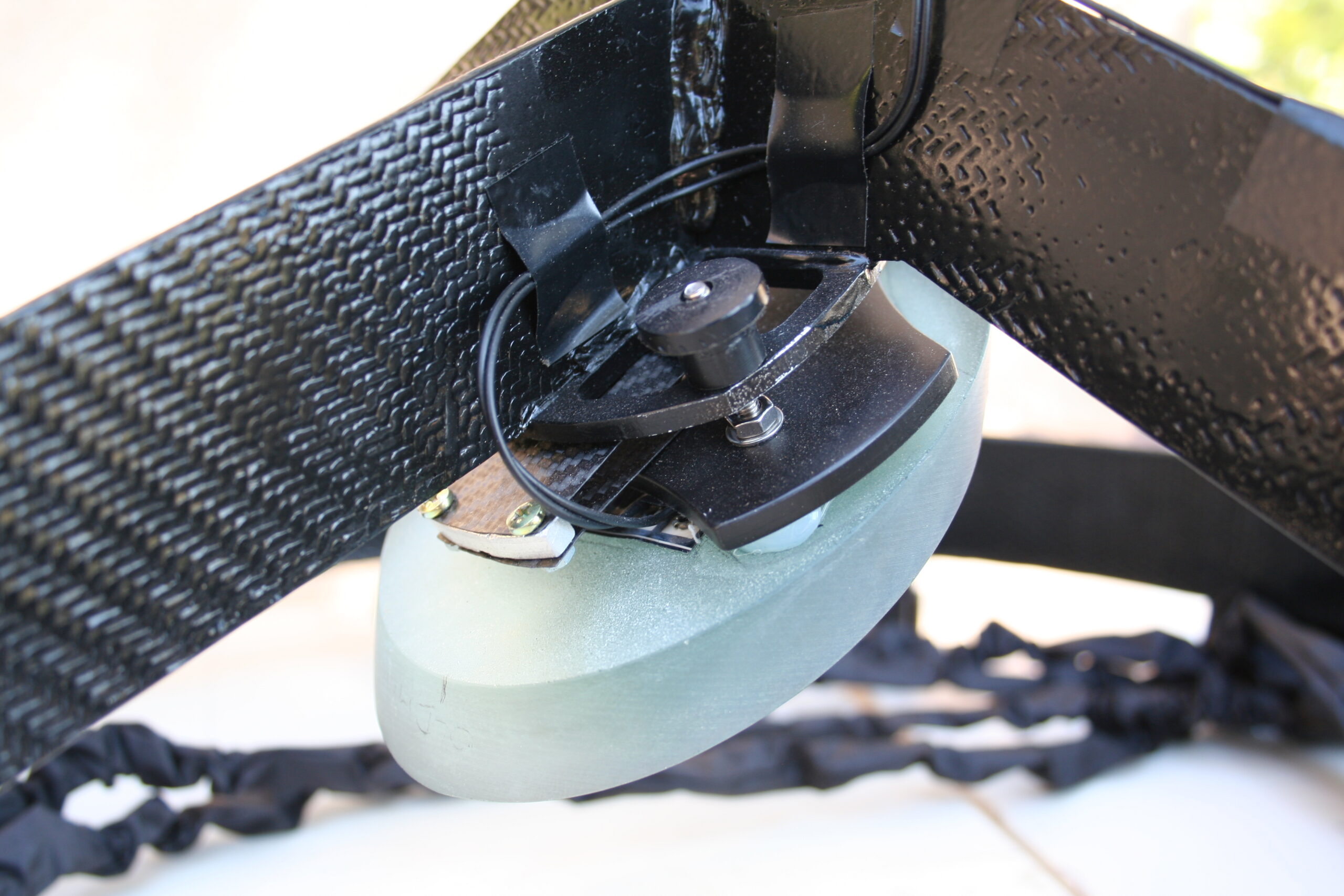
After experimenting with an α[2] of 30° in Sketchup, I decided that a α of 19° would be sufficient for my needs. This α would allow me to move the focuser 22 cm down the telescope and would not necessitate excessive baffling. The secondary mirror was glued[3] to an adjustable holder. I used a spring and ball design for this holder (see figure 14). The position of the holder is adjusted with two knobs. The telescope retains its collimation; no adjustments are needed during a night of observing. To warm the secondary mirror in case of dew, a heat foil was placed on the back of the secondary mirror (see figure 15).
Figure 15
>>>>Strings & Trusses
[1] http://www.davidlewistoronto.com/plop/
[2] See the paragraph on the lowrider concept
[3] Using Silicon glue