<<<<Strings & Trusses
Bearings
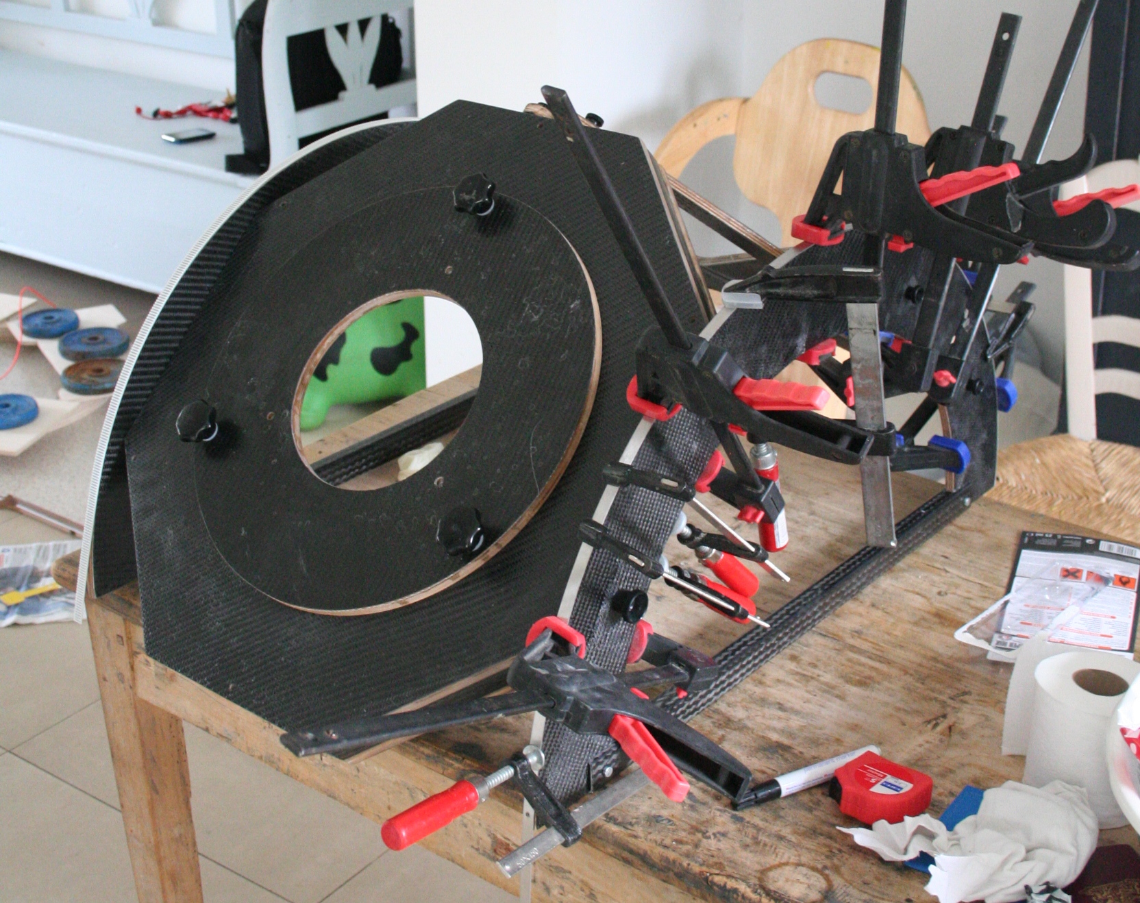
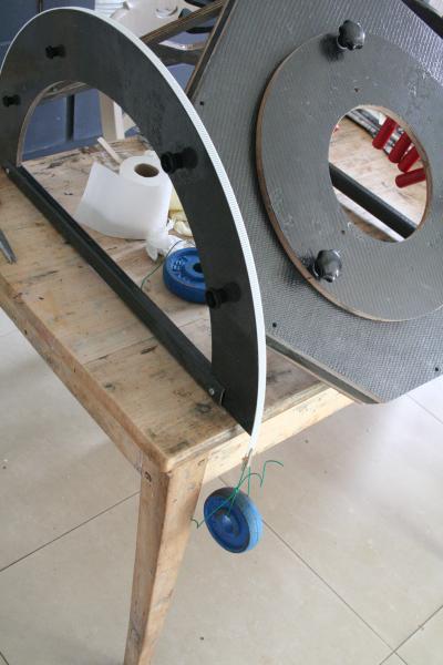
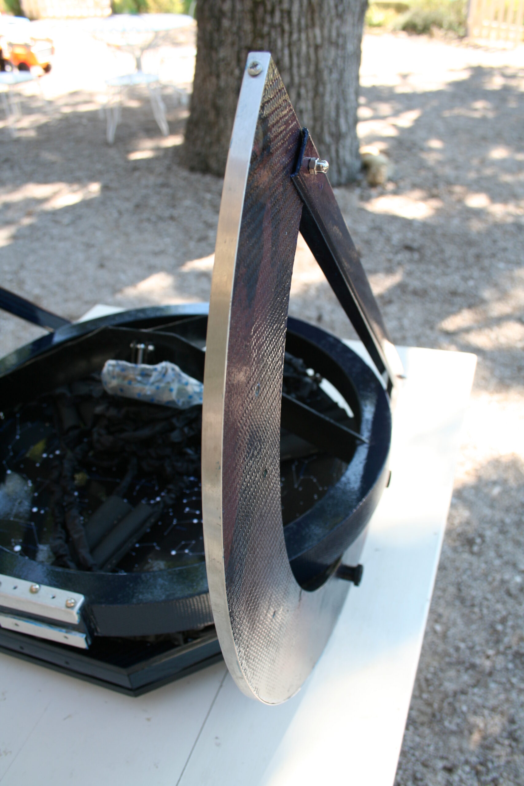
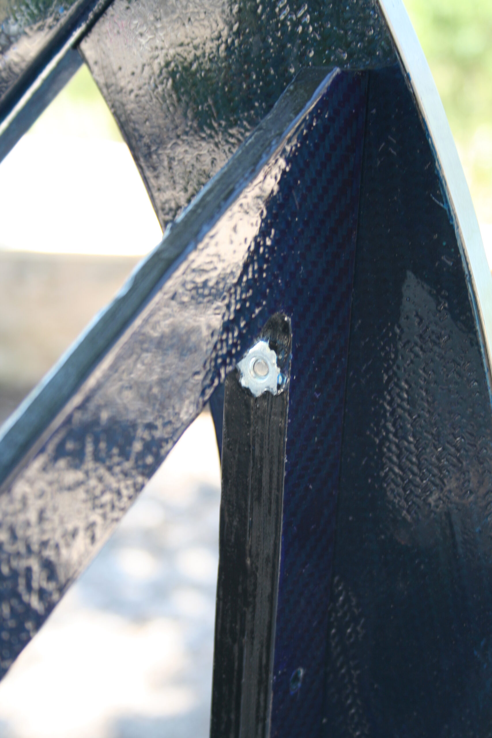
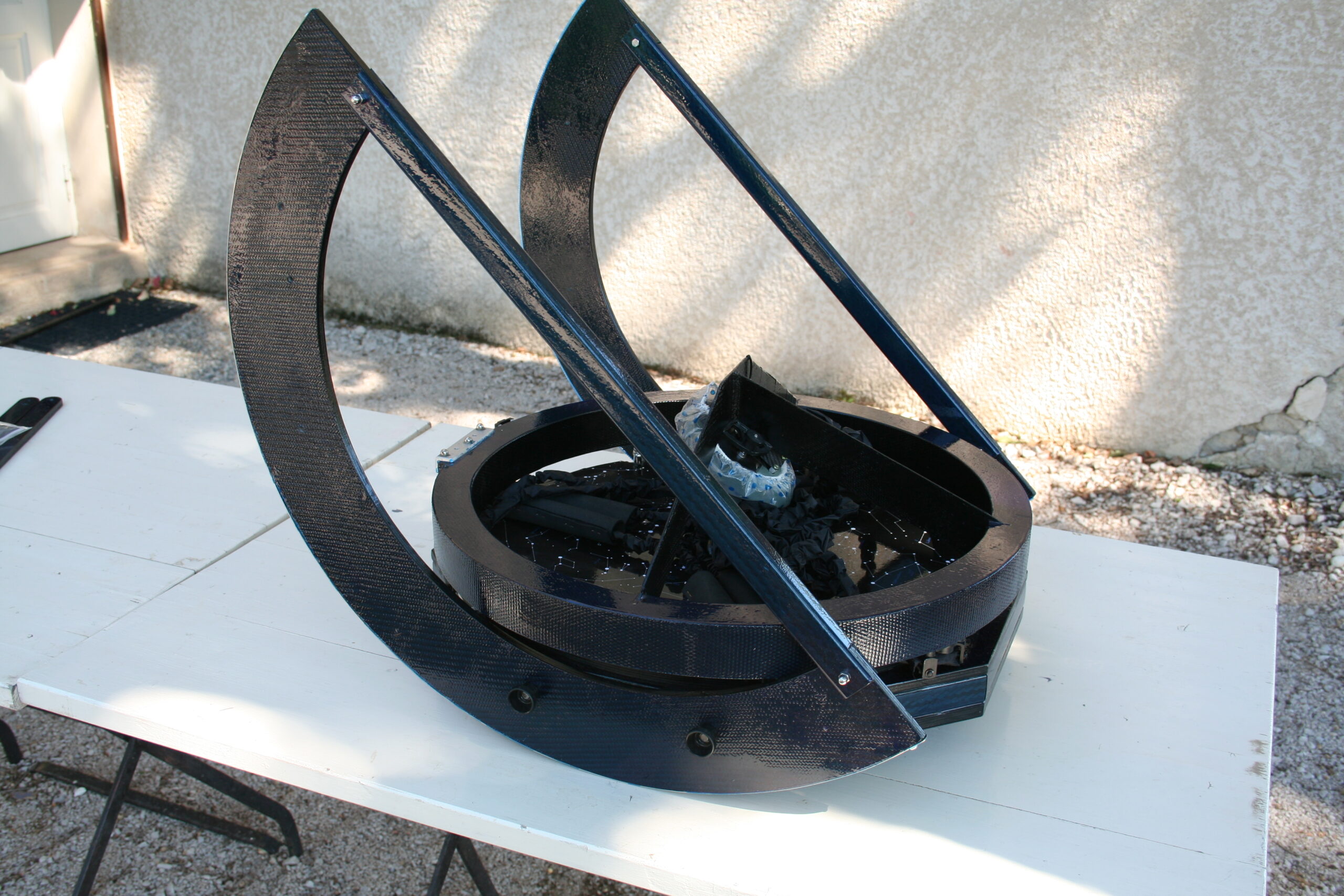
Thin altitude bearings are also a design feature that will add to a compact design. The bearings are made out of 9 mm wood laminated with carbon fiber. Since the carbon fiber did not add enough stiffness, a wooden frame was added which is connects the bearings but is also connected to the front of the mirror box. This frame was also laminated with carbon fiber. A timing belt was glued to one of the altitude bearing, the other was fitted with a steel strip (see figure 21). The carbon profiles on the altitude bearings serve to strengthen them and provide an easy way to lift the telescope. The three pieces (mirror box, altitude bearings and frame) can be transported separately, but are usually transported as a whole with the secondary ring resting on top.
Figure 21

Flexrocker
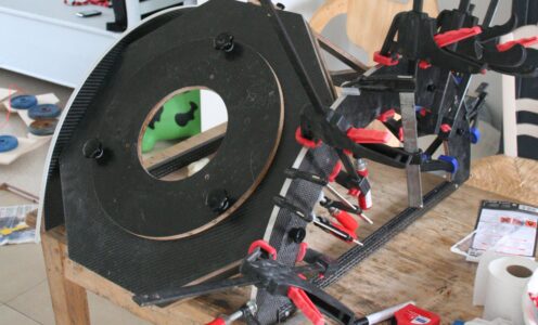
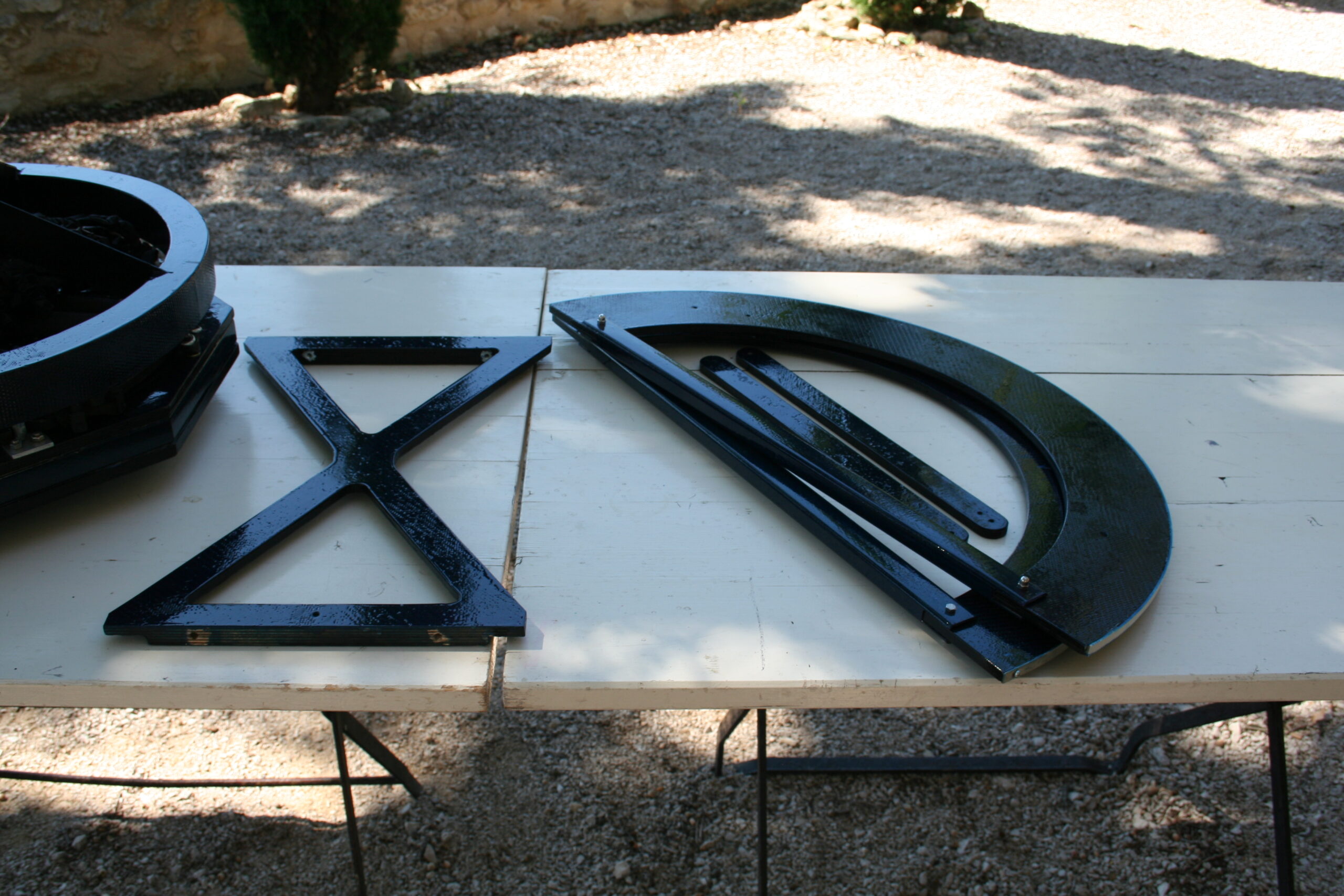
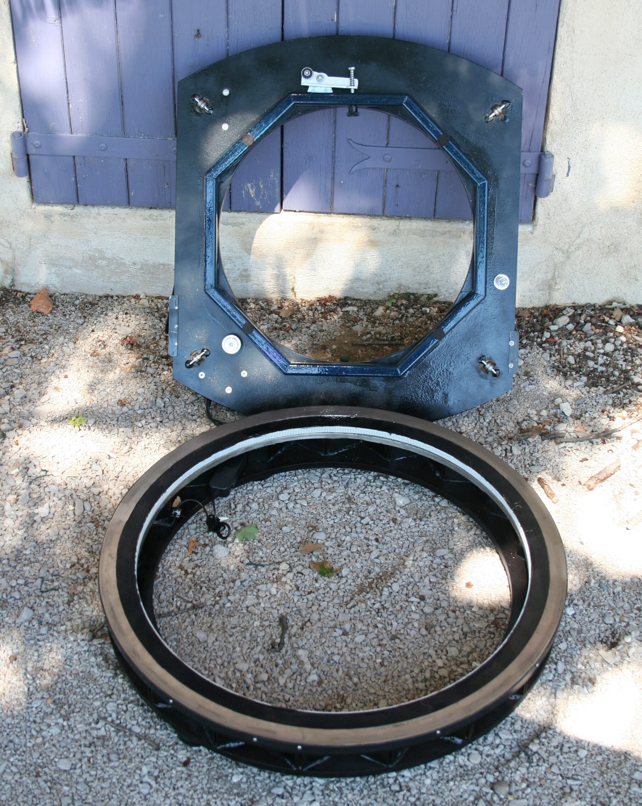
The rocker is made out of a 12 mm wooden plate which is reinforced with carbon fabric on the top. It is also strengthened by adding an octagon of carbon profile (the same as was used in the mirror box) on the underside (see figure 22). When the rocker is put on top of the ground ring this octagon disappears from view, creating a low but still compact rocker. The raisers are made out of 9 mm wood. Igus pillow block bearings in combination with two Delrin wheels and two timing belt pulleys were used as rollers for altitude bearings. The position of these wheels as compared to the bearings on the underside of the rocker is not traditional for a flexrocker. Unlike with a normal flexrocker, the weight of the telescope is not translated directly from the rocker to the groundring. Due to the octagon on the inside of the rocker and the stiffness of the raisers, the rocker plate is only a little flexible were it touches the groundring. This setup has a positive effect on the size of the groundring, which could be limited to 60 cm.
Figure 22 underside flexrocker & groundring


Groundring
The ground ring is composed of 3 layers of 12 mm wood with 9 mm wooden dividers between the second and third layer (see figure 23). On the outside of the ground ring a red neon wire is glue behind the plastic strip. When you turn it on, this creates a red glowing halo around the telescope. This was not done to deify the telescope but as a means to prevent anyone from walking into the telescope during public events of star parties.
Figure 23
Goto
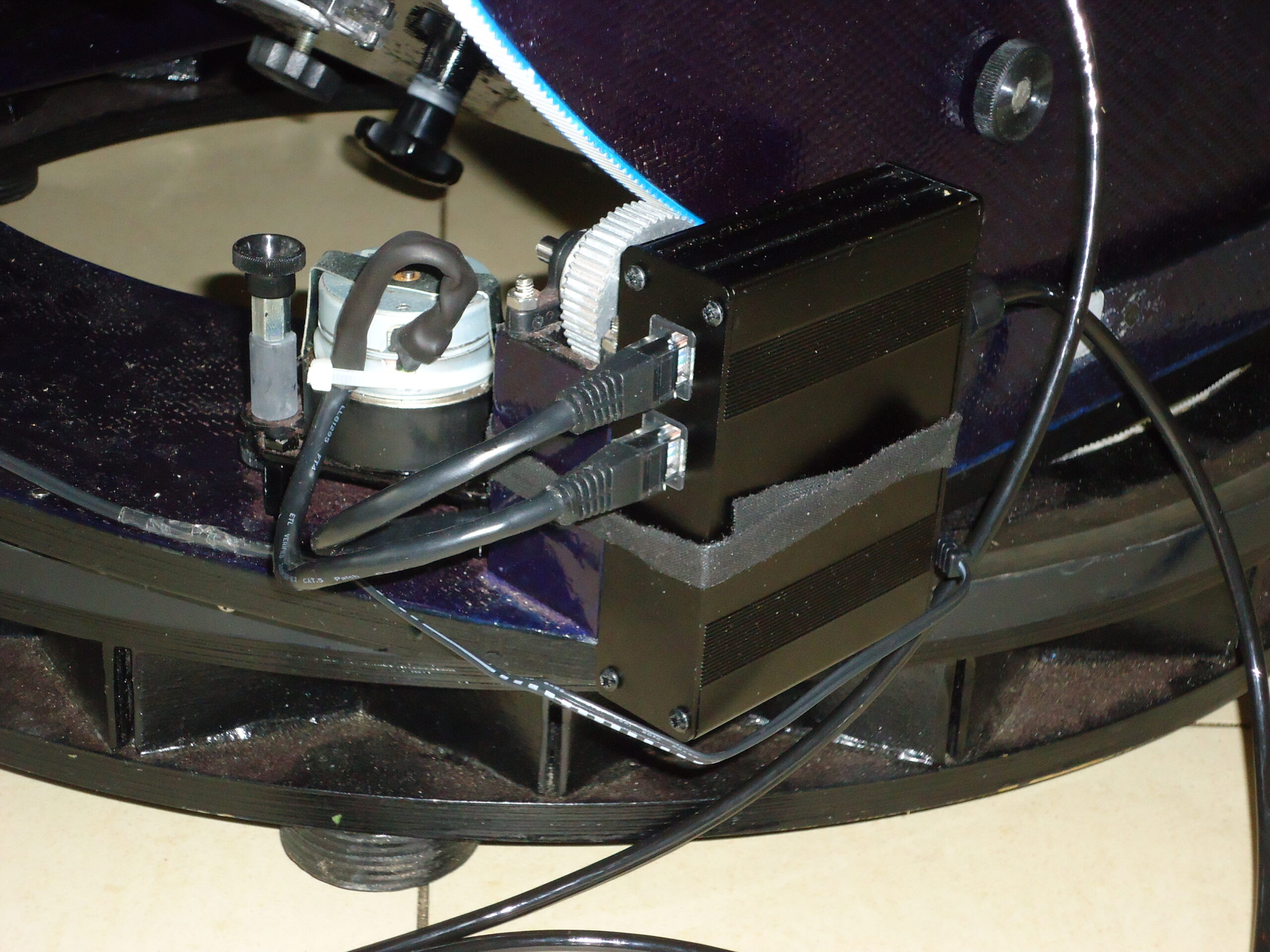
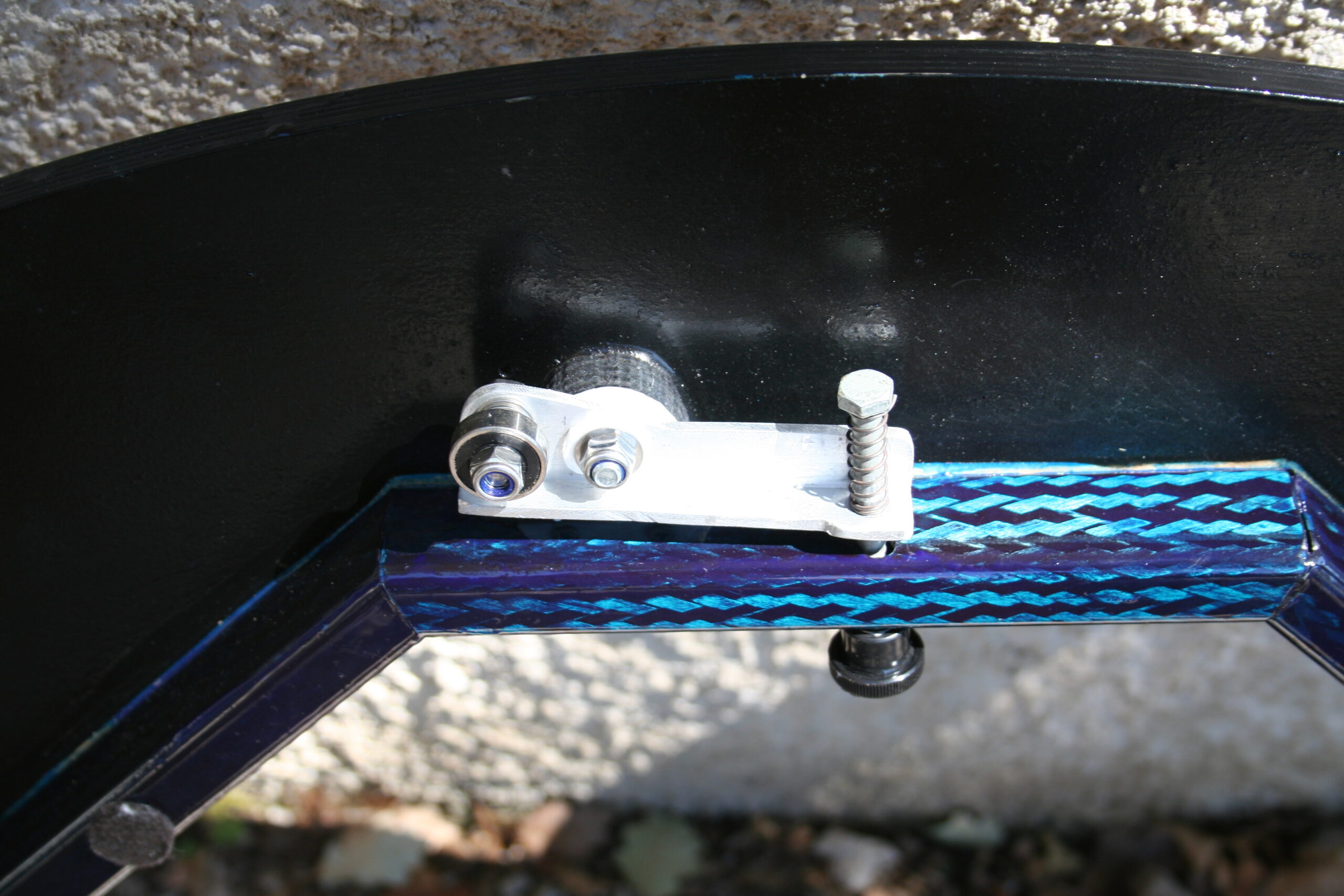
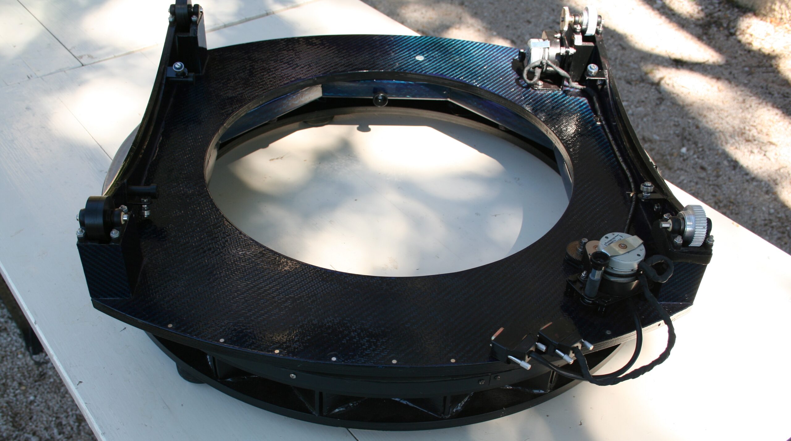
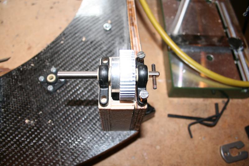
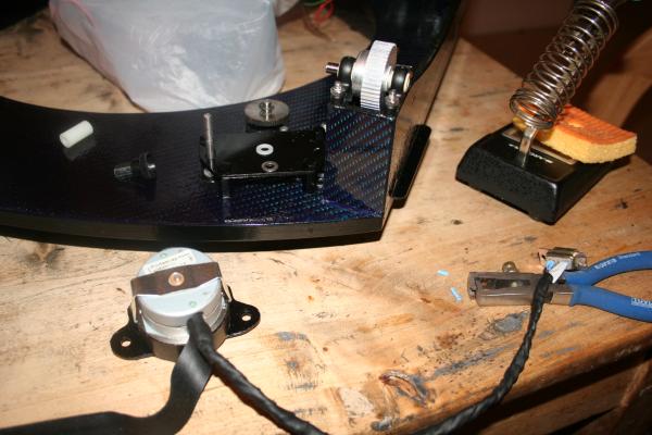
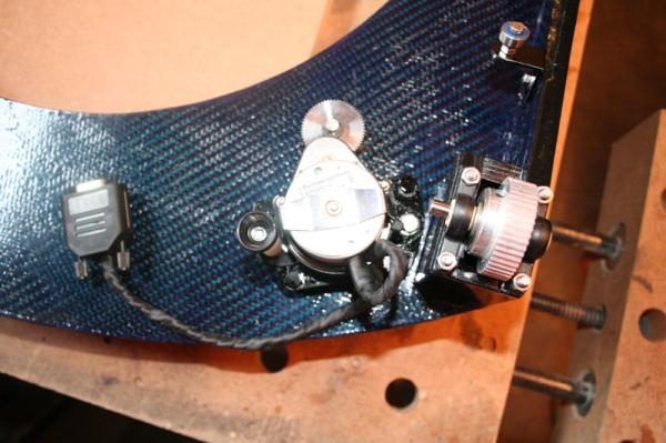
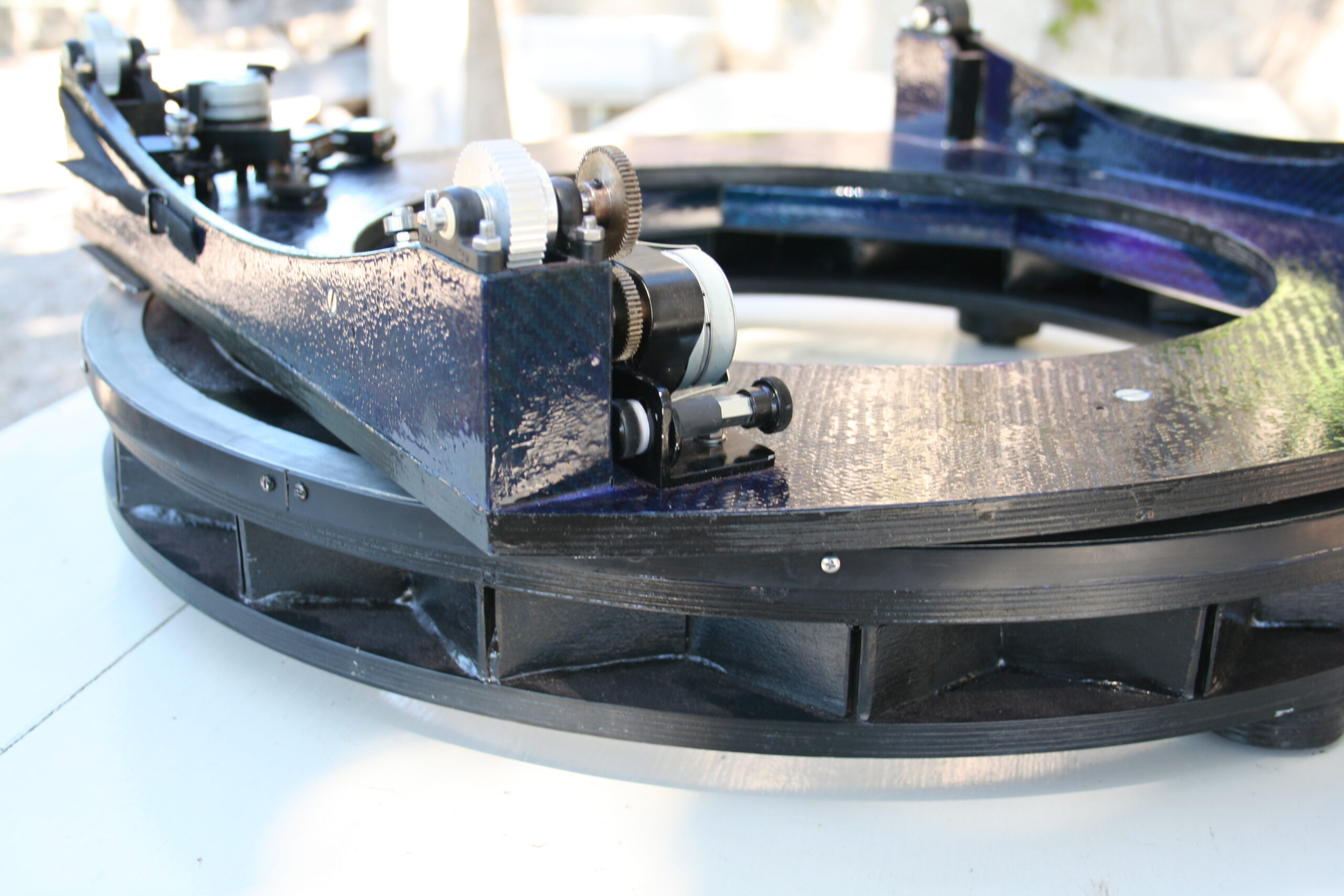
The mechanics necessary for computer control constituted of a timing belt on one of the altitude bearings and a stainless steel belt on the other. One of the side bearings is running on pulleys and the other side is running on two Delrin wheels. The front pulley is driven by a stepper motor. For control on the azimuth, a timing belt and stainless steel strip are glued to the inside of the ground ring. A pulley runs against the timing belt and two bearings (one of which is spring-loaded) run against the stainless steel strip. This pulley is also driven by a stepper motor (see images in figure 24).
Figure 24
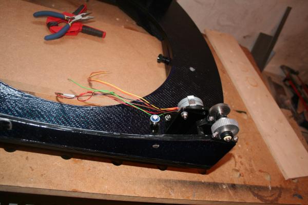
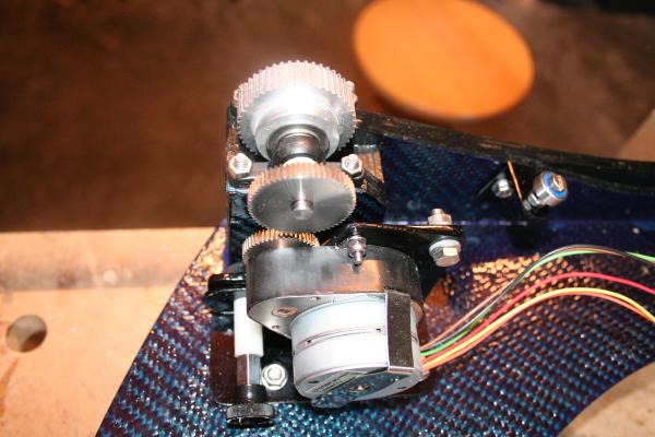
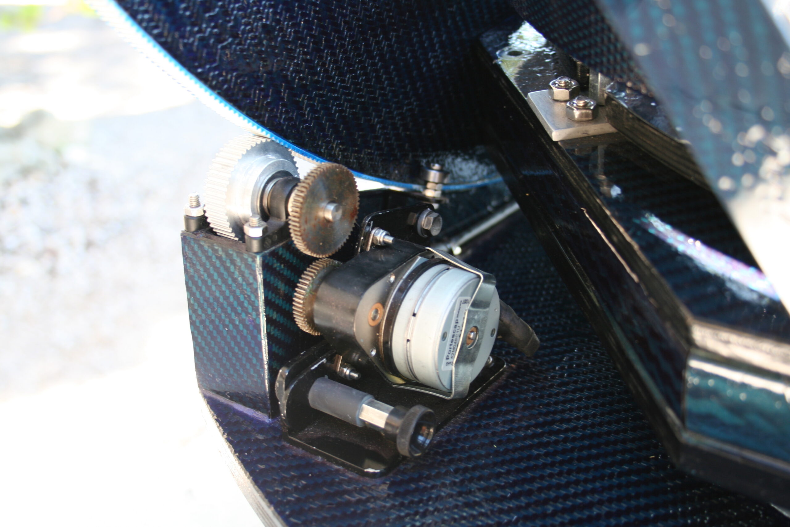
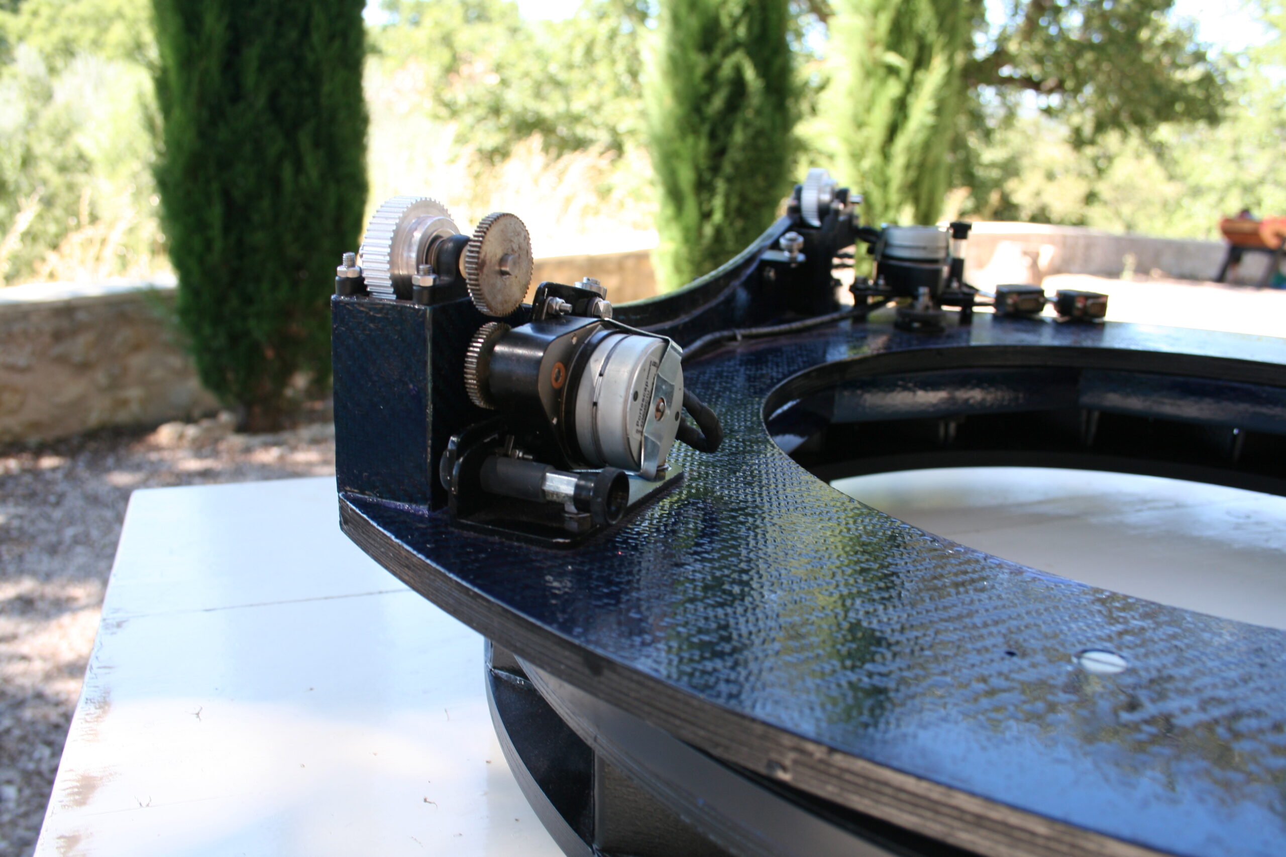
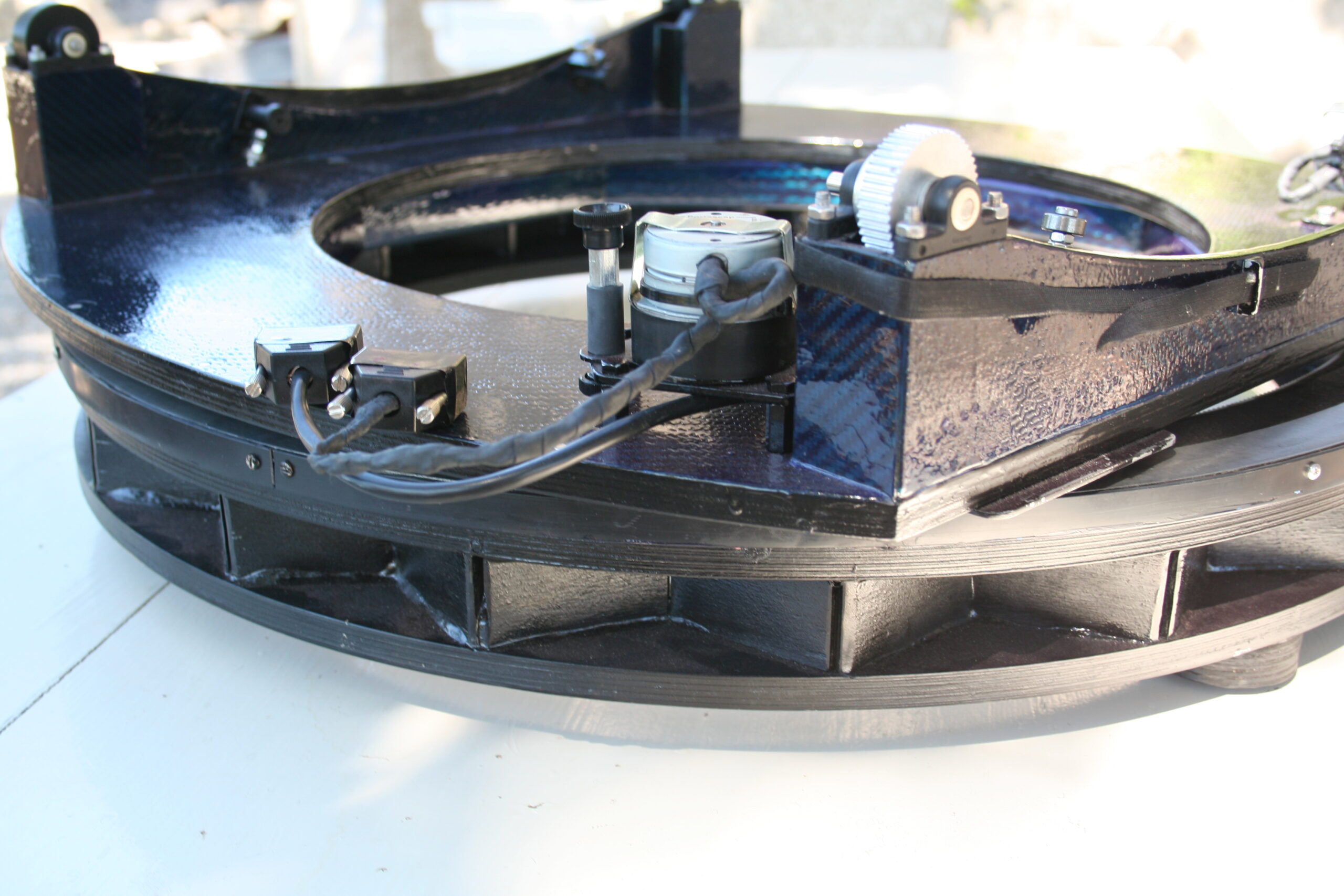
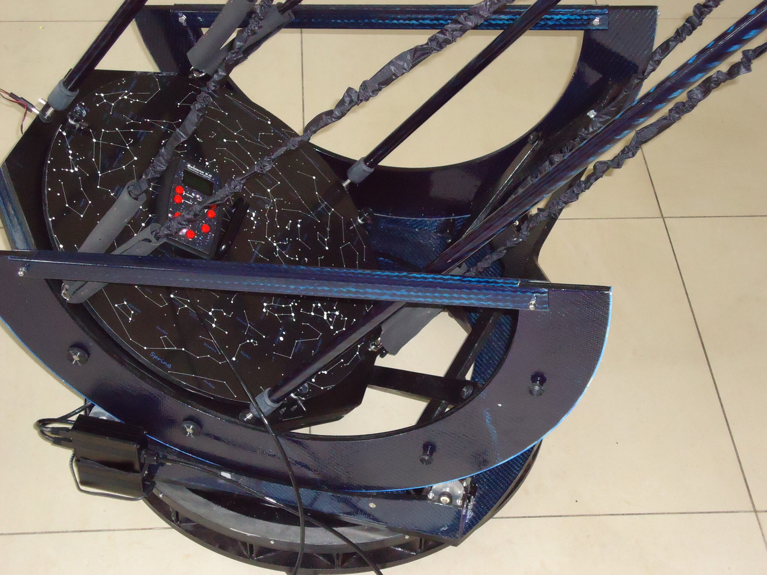
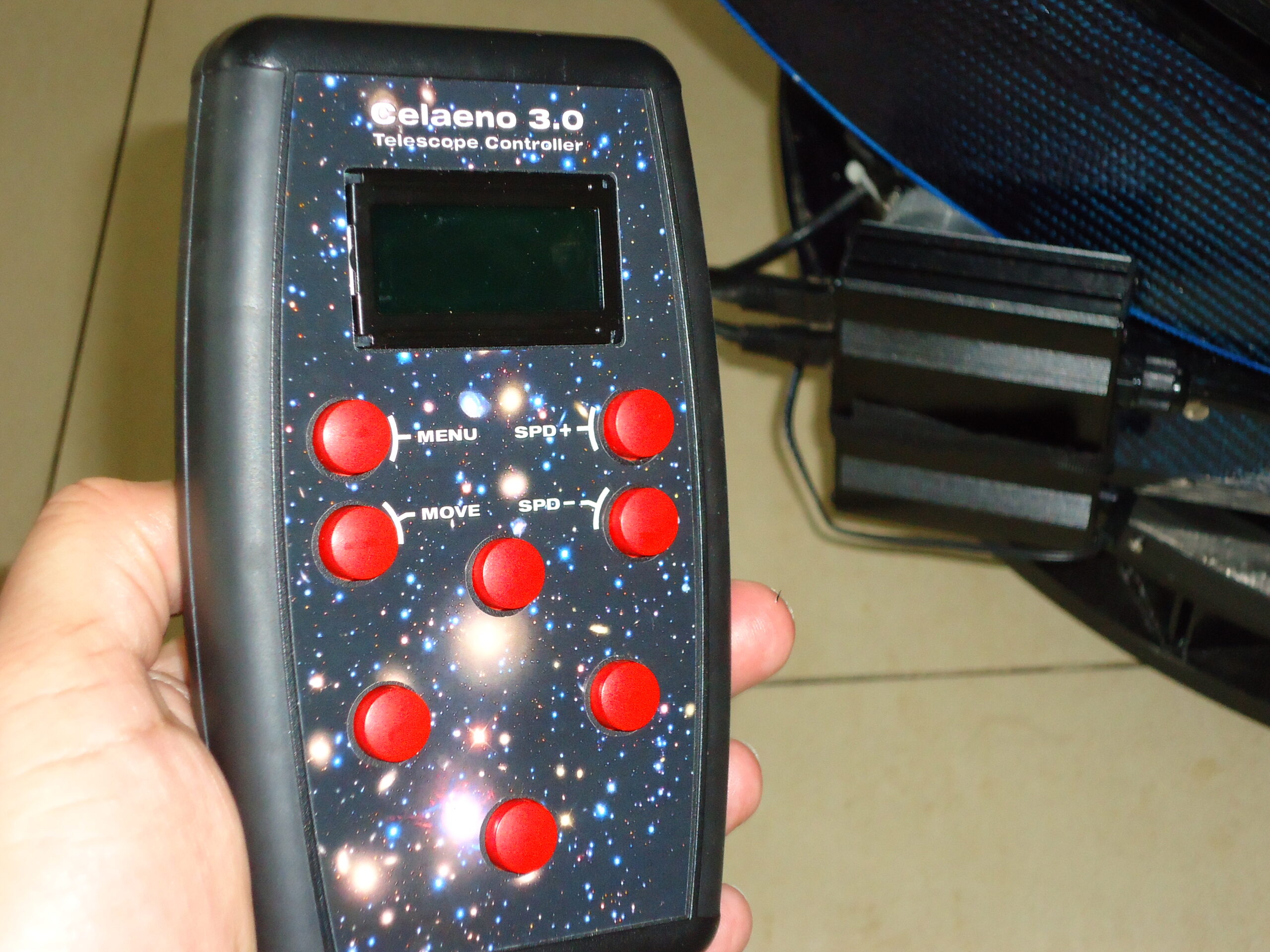
Increments on the alt and azimuth axes are such that they result in a micro step of less than 0.15 arcsec. This means that steps aren’t visible in the eyepiece until one magnifies over 800x. At normal magnification, the tracking motion smooth and steps aren’t visible. A Celano telescope controller is used for tracking and GOTO. The computer module and a lithium 12 volt 9800 mAh battery are attached to the rocker (see figure 25). The only cable connected to the telescope is the hand controller cable.
Figure 25